Posts

Showing posts from July, 2019

Bias adjustment 2

Image
Did some more work on the LDMOS amplifier. I believe I have the bias adjusted properly now. I'll do a little more testing then put some RF to it.

Bias adjustment

Image
Worked a little bit more on the LDMOS amplifier. I haven't gotten the bias adjusted correctly yet...

Fault protection code

Image
Today I wrote the fault protection code for the LDMOS amplifier. So it goes into fault mode if the temperature, current, or voltage goes too high.

Wiring complete

Image
The LDMOS amplifier wiring and construction is complete! Now all I have left is adjustment and RF testing.

Negative feedback installed

Image
Getting closer to putting RF to the beast... I have the negative feedback circuit installed. A few more connections, then test it with a 48 volt power supply, then do some voltage and bias measurements.

Current sensor installed

Image
I got the current sensor wired up, then programmed. Now the LCD screen displays main voltage, bias voltage and current draw. I also tested the high voltage mosfet switch, and loaded it with 83 ohms of power resistors. Looks like it is working fine with 5-600 mA. When the amp is running full power it should switch 5-7 amps at 48 volts. Hopefully it won't overheat at those current levels...
LCD installed

Image
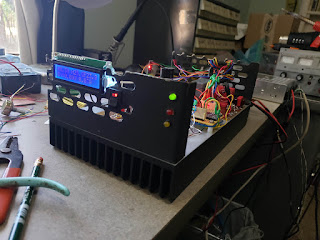
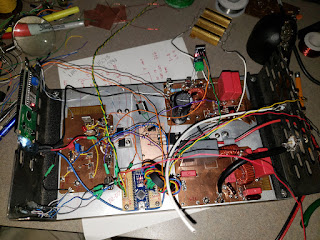
Made some more progress on the LDMOS amplifier. I got the high voltage measurement circuit built, the bias measurement, and the LCD installed.